Three phase induction motor 85% of the installed capacity of the industrial purposes because of good operating characteristics, low maintenance, easy construction , good speed regulation and absence of commutator. Three phase induction motor consist of two main parts
In an electric motor, the moving part is the rotor, which turns the shaft to deliver the mechanical power. The rotor usually has conductors laid into it that carry currents, which interact with the magnetic field of the stator to generate the forces that turn the shaft. Alternatively, some rotors carry permanent magnets, and the stator holds the conductors. Rotor of three phase induction motor are two different type one is squirrel cage rotor and other is wound rotor or slip ring rotor . wound rotor made up of aluminum or copper bars and the shaft of three phase motor supported on two bearings each ends. A slip ring or wound rotor is made up of three phase winding are jinxed at one end and other end connected to slip rings mounted on the rotor shaft.
The rotor is supported by bearings, which allow the rotor to turn on its axis. The bearings are in turn supported by the motor housing. The motor shaft extends through the bearings to the outside of the motor, where the load is applied
The distance between the rotor and stator is called the air gap. The air gap has important effects, and is generally as small as possible, as a large gap has a strong negative effect on performance. It is the main source of the low power factor at which motors operate. The magnetizing current increases with the air gap. For this reason, the air gap should be minimal. Very small gaps may pose mechanical problems in addition to noise and losses. Distance between the stator and rotor varies from 0.4 mm to 4 mm.
Windings are wires that are laid in coils, usually wrapped around a laminated soft iron magnetic core so as to form magnetic poles when energized with current.
Bearings mounted on the shaft, support the rotor and allow it to turn. Some motors use a fan also mounted on the rotor shaft to cool the motor when the shaft is rotating.
When three phase supply provided to the stator winding, it produces a rotating magnetic field and flux generates due to induced rotor current. According to the Faraday’s laws of electromagnetic induction. As these rotor conductors are shorted, the current starts to flow through in these conductors. direction of the rotor can be given by Lenz law - the direction of induced current will be in the opposite of the motion, This result the rotor starts rotating in the same direction of the stator rotating magnetic field
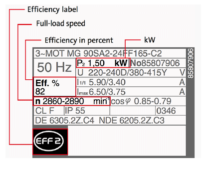
Horsepower Rating
Electric motors have a rated horsepower (HP) or kilo watt (Kw) that is determined by the amount of torque they can produce at their running or baseline speed. The nameplate shown indicates this motor is rated at 1.5 kW. The term “horsepower” comes from the rating of steam engines. Many years ago, James Watt invented the steam engine. At the time horses and mules were the means of travel and work. To sell his engines, Watt decided to compare the amount of power his steam engine could produce to the working ability of a horse.
Electrical motors are rated in horsepower or watt
Power is in general rated in watt (W) or horsepower (hp). The old imperial unit horsepower is equal to 746 watts (0.745 kW) or 33000 lb ft per minute (or 550 lb ft per second). The unit of electric power - 1 watt - is equal to the power produced by an electrical current of 1 amp at a potential difference of 1 volt
- 1 watt = 1 / 746 hp 1 hp = 746 watts = 0.76 kW
Hertz
The frequency of the sine waveform of the applied AC source is measured in hertz (Hz — cycles per second). Due to the parallel grid of the utility electrical power generation, transmission, and distribution, the standard frequency used throughout the United States and Canada is 60 Hz. The standard frequency of the parallel utility electrical-power grid in Europe is 50 Hz. The RPM of the electric motor depends on the applied frequency of the AC source and the number of magnetic poles per phase installed in the motor at the point of manufacture.
Revolutions per Minute, or RPM
indicate(s) the speed at which the electric motor will operate at rated load. Full-load speed is the speed at which rated full-load torque is delivered at rated power output. Normally, the full-load speed is given in RPM. This speed is sometimes called slip-speed or actual rotor speed.
Number of Phases
The term phase indicates the number of phases required in the electrical supply that the AC induction motor is designed to operate. Most industrial AC induction motors are rated 3-phase, which means that the AC power supply is three separate yet interconnected single-phase AC lines with the voltages across the respective windings 120° out of phase with each other. Other alternating current motors maybe rated as either single-phase or 2-phase. Although there are some single-phase AC induction motors used in industrial applications, the more predominant use is in residential applications. And, although 2-phase AC induction motors do exist, their use is extremely rare in industry operating in the United States.
Full-Load Amps
The full-load amps (FLA), full-load current (FLC), or rated-load current (RLC) of an AC induction motor (all three terms refer basically to the same thing) is the current drawn by the electric motor when it is operated at the rated load, rated voltage, and rated frequency (AC motors) as found on the motor nameplate.
Voltage Rating
This data tells you at which voltage the motor is made to operate. When the motor is used at other voltages than the voltage indicated on the nameplate, its performance will be affected.
Power factor
Also given on the nameplate as “P.F.” or PF,” power factor is the ratio of the active power (W) to the apparent power (VA) expressed as a percentage. It is numerically equal to the cosine of the angle of lag of the input current with respect to its voltage, multiplied by 100. For an induction motor, power factor also varies with load. The nameplate provides the power factor for the motor at full load.
What is Ingress protection (IP)
Ingress protection ratings or IP ratings, refer to the level of protection offered by an electrical enclosure, against solids and liquids
The numbers that follow IP each have a specific meaning. The first indicates the degree of protection (of people) from moving parts, as well as the protection of enclosed equipment from foreign bodies. The second defines the protection level that the enclosure enjoys from various forms of moisture (drips, sprays, submersion etc). The tables below should help make sense of it:
Protection against solid objects
0 – No protection/ No test required
1 – Protected against objects greater than 50mm diameter
2 – Protected against objects greater than 12.5mm diameter, such as a finger
3 – Protected against objects greater than 2.5mm
4 – Protected against objects greater than 1.0mm such as wire
5 – Ingress of dust is not totally prevented but dust does not enter in harmful quantities
to interfere with the correct operation or impair safety
6 – No ingress of dust permitted
Protection against water
0 – No protection / No test required
1 – Protected against falling drops of water
2 – Protected against drops falling at 15° in 4 fixed positions
3 – Low pressure spray – similar to shower head at up to 60° from vertical tested using an oscillating tube with an arc of 60° for ten minutes
4 – Low pressure spray – similar to shower head – as per numeral 3 but 180° for 10 minutes
5 – Medium pressure jet – 6.3mm diameter, similar to garden hose – from any angle for 3 minutes at a distance of 2.5-3 meters.
6 – High pressure jet – 12.5mm diameter, similar to fire hose – from any angle for 3 minutes at a distance of 2.5-3 meters.
7 – Immersion – for temporary immersion in water under set conditions – 1 meter for 30 minutes
8 – Protected against the effects of continuous immersion in water, ingress of water in quantities causing harmful effects shall not be possible.
ELECTRIC MOTORS – INSULATION CLASSES
Insulation class indicates the maximum temperature the motor insulation can withstand without failure. The following table shows the maximum operating temperatures for commonly used classes of insulation. Electric motor's windings temperature must not exceed the permissible temperature shown in the insulation class table. For example F class insulated electric motor's winding temperature cannot exceed 155° C. Electric motor manufacturers usually permit for B class insulation temperatures while using F class insulation materials to get 25 °C safety. This ensures safety for higher ambient temperatures, high altitude or high and low voltage operating conditions.
STRIPPING OF MOTORSTATOR WINDING
If the entire stator must be rewound it would be very difficult and time consuming to remove the windings from the core. The winding are usually extremely hard because of the varnish. Usually the coils on the back side of the stator are cut off with a chisel as shown in the figure. Then the stator is placed in a burn-off oven for some time at approximately 2000c. The oven may be gas fired or electric. It is important that the heating be controlled to prevent warping of the frames and damage to the lamination plating. Removing the rest of the coils is relatively simple because the remaining coils may be pushed through the slots from the other side of the winding.
During the process of stripping the number of turns in each of the coils must be counted. This information is then recorded on the data sheet. At this time, also, the size of the wire is measured, usually by means of a micrometer after it is stripped of its insulation. It is then recorded on the data sheet.
INSULATION OF MOTORSTATOR SLOTS
Before placing the winding in the slot some form of insulation must be installed so that the wires do not touch any part of the iron core. Different types of material are available for this purpose.
The insulation is cut as shown in the figure. It must be approximately 5mm longer than the walls of the slot. The ends of the insulation are often cuffed to prevent them from sliding in the slot and possibly being the cause of a grounded coil. This insulation material is manufactured and sold in rolls and sheets in assorted widths and thicknesses. Cuffed insulation is cut to a length to fit the slots; an insulation cutter is used for this purpose. For the average size of fractional-horse power motors, insulation paper approximately 0.15 to 0.35mm thick is suitable for slot insulation.
The insulation between the running and starting winding is generally 0.15m thick. The figure also shows the manner of installing a feeder strip of insulation that covers the edges of the slot while winding.
This feeder may be removed after winding the coil or its ends may be folded over and left in the coil.
PROCEDURE OF INSERTING COIL
The turns of the coils are inserted one by one into semi closed slots.
Use the following procedure: Spread out the turns on one side of the coil and hold the coil at an angle so that all the turns can be fed into the slot. The figure shows this procedure. Make sure that each turn is placed between the wires are placed between the insulation and the iron core by mistake and a ground results.
When the top side is placed into the slot, slip a wooden or formed fiber wedge (round or square) over the top coil. This should extend to as the slot insulation beyond the slot ends. As each group of coils is the slot, phase insulation must be used between groups. Heavy separators are placed between coils in the slot and wedges over the top coils. Slot wedges are inserted to held the coils securely in place.
BAKING AND VARNISHING
When all the Connections between poles of the windings have been completed and tested and the flexible leads to the power line attached of tied, the stator should be placed in a baking oven at a temperature of approximately 1000C and preheated for a short period of time, approximately 1 hour.
This removes moisture from the windings and increase the penetration of the varnish. The stator is then dipped into a container of insulation varnish compatible with the type of windings wire used. It is important to remember that the varnish must be thin enough to penetrate the winding and thick enough to leave an adequate film when baked. The varnish may become thickened due to evaporation of the thinning fluid. If this happens, use a thinner recommended by the manufacturer.
After the winding has been soaked in the varnish for approximately one – half hour or until all bubbling has ceased, it is removed from the container and allowed to drip. After it has stopped dripping it is again placed into the baking oven and baked for several hours as shown in the diagram. In using any type of varnish, make certain the manufacturer’s recommendations and directions are followed. When the stator is removed from the oven, the inner surface of the core should be scraped to remove the adhering varnish, so that there will be sufficient space for the rotor to turn freely.
Dipping and baking bonds the entire winding into a solid mass that is not subject to movement. It seals the winding against and foreign material and increase the mechanical and dielectric strength of winding wires.
E-mail - wegiriyalahiru7@gmaul.com


Comments
Post a Comment